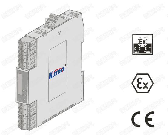
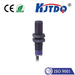
KJT intrinsically safe NAMUR proximity switches are mainly used in equipment and environments that require explosion protection, such as coal mines, petrochemicals, etc. The NAMUR signal is the most widely used intrinsically safe digital input and frequency input standard signal in the world. The earliest is the German standard (DIN19234). Later it became a European standard (EN 50227, DIN EN 60947-5-6). The NAMUR signal is a passive 2-wire system, nominal 8VDC power supply, 1mA and 3mA switching signals. NAMUR type sensors are intrinsically safe explosion-proof instruments and are usually used in conjunction with isolated safety barriers.

· Receive the contact switch or NAMUR proximity switch signal from the hazardous area, and transmit it to the control system or other instruments in the safe area in the form of relay contact output through isolation.
·Dual channel, two inputs, two outputs.
· DC power supply mode, power supply-input-output and isolation between channels.
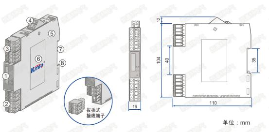
· Adopts standard 35mm DIN rail card-type installation. Removable plug terminals, spring-pressed connection.


Precautions:
· This instrument is "intrinsically safe" electrical equipment and should be installed in a safe place.
· Installation, electrical connections and operation should be carried out by professionals with technical qualifications as electricians.
· Please observe the installation requirements stated. Please observe the applicable regulatory and safety regulations as well as the general technical rules.
· Please refer to this instruction manual for technical data.
· It is prohibited to make any modifications to the internal circuit of the instrument and to repair the instrument without authorization.
· The instrument may only be replaced with a similar instrument, and only the manufacturer may perform repair operations.
· The protection level of this instrument is IP20 (IEC 60529/EN 60529) and is suitable for use in a clean and dry environment. Do not load the equipment beyond its design capabilities.
· When measuring on the intrinsically safe side, the regulations for connecting intrinsically safe electrical equipment must be observed. Only equipment approved for use in intrinsically safe circuits may be used within such circuits.
· Installation or disassembly, connection or disconnection of wiring is only allowed when the instrument is powered off.
· If the instrument is damaged, improperly loaded or has a functional failure, shut down the instrument and evacuate it immediately.
◆Power supply
Power supply voltage range: 20~30VDC
Rated power supply voltage: 24V DC
Current consumption (24VDC power supply, relay output): <60 mA ◆ Input from hazardous area
Contact switch or NAMUR proximity switch according to DIN 19234. Open circuit voltage: 8V±0.5V
Switching threshold: 1.2~2.1mA
Hysteresis: 0.2mA (typ.)
◆Output to safe area
● Output to safe area
Output type: ① Relay contact; ② Transistor; ③ Level signal (please select the output type when ordering)
① Relay contacts
Contact characteristics: 24VDC, 2A;
Load type: Resistive load
Response time: ≤10ms
② Transistor
External power supply voltage: ≤40V
Drive output current: ≤40mA
Transistor collector output High level: VCC; Low level: ≤2.5V
Transistor emitter output High level: VCC-2.5V; Low level: ≤ 0.5V
③ Level signal
High level: 4.5V ~ 5.5V
Low level: ≤0.5V
High level driving capability: ≤20mA
◆Explanation of input/output characteristics (in-phase control)
The factory setting state of the instrument is that the input and output are in the same phase, that is, the input switch is closed and the output relay is also closed. The output status indicator light on the instrument panel is on.
◆ Instrument indicator light
LED indicators on the instrument panel:
PWR is the power indicator light (power is on, the indicator light is on)
OUT1 is the first output status indicator light (the light is on, the output relay contact is closed)
OUT2 is the second output status indicator light (the light is on, the output relay contact is closed)
◆Comprehensive general parameters
Isolation capability: between input-output-power supply 2.5KV, 1min, 50Hz
Insulation resistance: between input-output-power supply ≥1 00MΩ / 500VDC Working environment temperature: -20~+60℃
Storage environment temperature: -40~+80℃
Environmental humidity range: 5~95%RH (no condensation)
Shell material: flame retardant ABS
Protection level: IP 20
Overall dimensions/machine weight: 16×1 16×1 10 (mm); about 110g~120g
Suitable for connected field devices and hazardous areas: NAMUR proximity switches in accordance with DIN 19234. Zone 0, Zone 1, Zone 2; IIA, IIB, IIC.
◆Safety and explosion-proof certification parameters
Explosion-proof grade mark: [Exia Ga]IIC
Safety parameters: Um = 250V AC/DC Uo = 10.5V DC Io = 22mA
Po =57.8mW Lo = 3 mH Co = 1.7μF